3 Phase Transformer Primary and Secondary Current Calculation
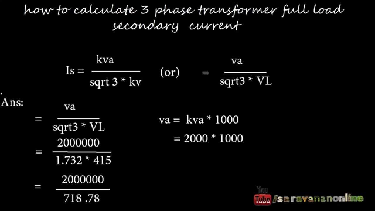
I A S kVA 1000 V V. For 1 phase transformer use following formula.
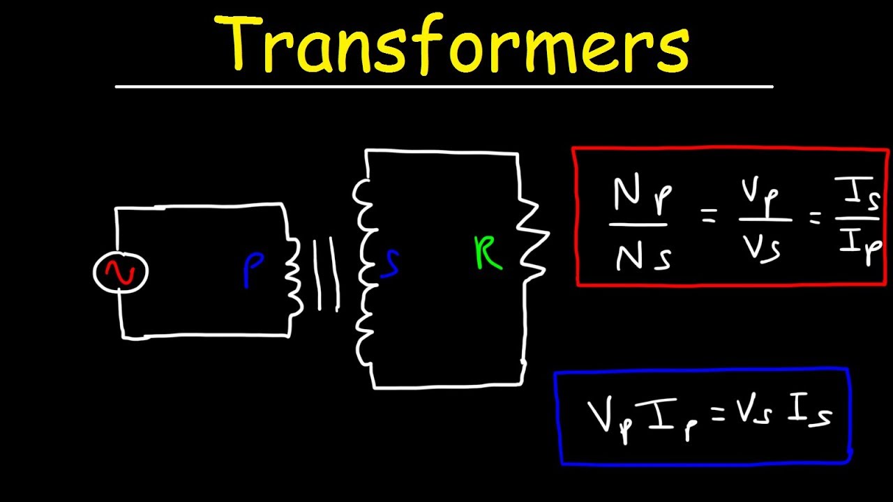
Transformers Physics Problems Voltage Current Power Calculations Electromagnetic Induction Youtube
Figure 6 Bar Primary Type Current Transformer CT having Single Primary turn with the Primary Conductor embedded Go back to contents.

. In transformer primary is delta connection and secondary is star connection the primary v1110kv v222kv and power is 16 mva how to calculate current i1 and i2 If im using the formual p 3vphiphcos fi what is the value of cos fi. It can be shown that voltages currents and impedances in a per-unit system will have the same values whether they are referred to primary or secondary of a transformer. The three phases or hot wires plus a center tapped neutral comes from the transformer.
208V and 240V 1 3 Phase. For 3 phase transformer use following formula. Any Deadline - Any Subject.
Receive your papers on. Get Free Android App Download Electrical Technology App Now. The primary side of the transformer configured in Wye is connected to the 72 kV distribution lines.
We cover any subject you have. Transformer Phase Shift. An XSLT element is an element in the XSLT namespace whose syntax and semantics are defined in this specification For a non-normative list of XSLT elements see D Element Syntax Summary.
Wye-Wye and Delta-Delta transformers do not cause any phase shift from primary to secondary. To calculate the transformer secondary rated current along with the collective available short circuit current the following equations can be used 1a Secondary current calculation example The secondary current can be calculated using the 34kVA power rating of the isolation transformer fed with a 460V line. Step 3 Calculate the short.
Ring type is the most usual type of core-balance current transformer CBCT. 253 Core-Balance Current Transformers. Type of Supply Voltage.
Voltage is increased on the primary until full load current flows in the secondary. What size secondary conductor can be used for a 45kVA continuously loaded 3-phase 480V-120208V transformer. It depends on the core construction and magnetic properties of the core materials like lamination winding thickness lamination resistance component density.
Special application metering CTs are a special category in which it is desired that the CT should accurately measure the current from 1 to 120 of the rated current. In this document the specification of each XSLT element is preceded by a summary of its syntax in the form of a model for elements of that element type. If the transformer is rated in MVA means the formula will be.
A single phase transformer has 480 turns on the primary winding and 90 turns on the secondary winding. Therefore even at absolute zero atoms and molecules retain some vibrational motionApart from atoms and molecules the. The maximum flux in the core.
Increase the voltage gradually to 2030405060708090 of the rated knee point of the CT and note down the secondary current. It is caused by the generated alternating flux in the transformer core. Fault Current At Transformer Secondary IscL-NI L-NTotal Impedance 2.
Apply 5-10 voltage of the knee point voltage to the secondary of the CT by auto-transformer. And are the inductances of the primary and secondary coil respectively and is the mutual inductance between the coils. Note for rated secondary current As shown previously the smaller the CT burden in voltamperes the better higher the actual accuracy limit factor.
The Current Transformer CT. Get all these features for 6577 FREE. The transformer secondary is short circuited.
The phase difference between the current and the. Unlike in classical mechanics quantum systems constantly fluctuate in their lowest energy state as described by the Heisenberg uncertainty principle. Available Fault Current Calculation Isc Calculation.
Cable is passing through the centre of CT and in that way forms the primary winding. Zero-point energy ZPE is the lowest possible energy that a quantum mechanical system may have. Secondary Voltage Assue 440 volts Impedance Youll get it from the name plate of transformer for our example assume 5 Step 2 Calculate Full Load Current.
Delta-Wye transformers have a 30-degree phase shift which is discussed below. Sometimes core loss is known as Magnetizing current Loss or Constant Loss. Now increase the voltage to 100 of KPV and note down the current.
The International Electro-Technical Exhibition of 1891 featuring the long-distance transmission of high-power three-phase electric current. This type of CT is used for revenue meters and in energy meters. In general the full load current is equal to.
Secondary Current Transformer VA Secondary Voltage 1732 I. This applied voltage divided by the rated primary voltage times 100 is the impedance of the transformer. Is a type of instrument transformer that is designed to produce an alternating current in its secondary winding which is proportional to the current being measured in its primaryCurrent transformers reduce high voltage currents to a much lower value and provide a convenient way of safely monitoring the actual electrical current flowing in an AC.
B Being a 3-phase unit emergency backup controls are sensitive to phase current imbalance and managing this situation across the 3 phases for the emergency circuits is problematic. There are four different ways in which single phase transformers can be connected to form three phase banks. Determine the secondary current rating.
1 2 1 2. A current transformer is ideally a short-circuited transformer where the secondary ter-minal voltage is zero and the magnetizing current is negligible. 85 For instance for voltage we can prove that the per unit voltages of two.
This equation gives current transformation in proportion to the primary and secondary turns. Between 1885 and 1890 poly-phase currents combined with electromagnetic induction and practical AC induction motors were developed. Transformer impedance is determined as follows.
For a 480 Volt rated primary if 96 volts causes. Calculation of the actual accuracy limit factor. 1 Calculate Short Circuit Current at Substation.
Wiring of 240V 208V 120V 1 3-Phase High Leg Delta Breaker Box. When changing to 1A rated CT secondary current instead of 5 A the burden in voltamperes will drop to a level of 125 of what it was. It was held between 16 May and 19 October on the disused site of the.
The output voltage levels of the transformer from the secondary side wires in Wye are 277V 1-Phase and 480V 1-Phase 3-Phase. Set the deadline and keep calm. This is the principle behind a transformer.
In the delta secondary each hot connects to two separate transformers. The voltage peaks occur earlier in each cycle than the current peaks. Voltage transformers For a transformer in no load the following is valid.
Transformer full load current I A in amps for single-phase transformer is equal to 1000 times of transformer rating S kVA in kVA kilo Volt-Amp divided by the primary V P-V or secondary voltage V S-V in volts of the transformer. Can be used to calculate the forces between two conductors in the event of a 3 phase. Essay Help for Your Convenience.
Lets calculate full load current in our example. C Being a 3-phase unit implies rotating machinery circuits may be in use and the inverter is sensitive to inrush currents with strict limits imposed. Fault Current At Main Panel.
Core Loss or Iron loss. If the secondary rated current is 5A this meter shall measure current from 50 mA to 6A accurately. Note down the secondary current.
The maximum value of the magnetic flux density is 11T when 2200 volts 50Hz is applied to the transformer primary winding.

How To Calculate Three Phase Transformer Full Load Secondary Current Youtube
Question Video Finding The Number Of Turns On The Primary Coil Of A Transformer Nagwa
How To Calculate Three Phase Transformer Full Load Secondary Current Youtube
![]()
Three Phase Transformer Connections And Basics
No comments for "3 Phase Transformer Primary and Secondary Current Calculation"
Post a Comment